

The End-fed Half-wave (EFHW)
…why is it the World’s most popular portable antenna?
In early 2014 I conducted an online survey for portable antennas. The survey asked just one question “What is your favourite portable antenna?”. The rationale behind this was not to find what people thought was necessarily the best-performing portable antenna but rather to find out what they were most likely to actually use. The survey was copied to various groups such as the QRP-L mailing list, GQRP and the SOTAbeams mailing list to name but a few. There was a bias towards QRP sources but the question was not directly QRP related. Respondents were given a number of options to choose from. The table below summarises the responses
|
Answer Choices– |
Responses– |
|
EFHW |
17.55% 53 |
|
Linked dipole |
14.57% 44 |
|
Single band dipole |
11.59% 35 |
|
Random length endfed |
11.59% 35 |
|
Ground-plane |
10.93% 33 |
|
Other |
10.60% 32 |
|
Doublet |
9.27% 28 |
|
Multiband loaded dipole |
6.29% 19 |
|
Magnetic loop |
5.96% 18 |
|
W3EDP |
1.66% 5 |
|
Total |
302 |
There is obviously a fair spread of views on the favourite antenna. As might be expected the “other” category included a variety of answers – mostly various forms of multiband verticals. The clear winner with over 17% of the vote is the end-fed half-wave. With 302 responses the survey has some validity. The figures give rise to a margin of error of 5.6% and a confidence interval of 92%, so it’s a very good indication! So what’s the deal with an end-fed half-wave (EFHW)?
The EFHW under the microscope
A half-wave conductor when excited at its resonant frequency will display a voltage and current distribution as shown in Figure 1.
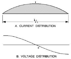
Figure 1. Source: http://electriciantraining.tpub.com/
The current distribution is sinusoidal with a node (minimum) at each end and an anti-node (maximum) in the middle. At the centre of the half-wave the impedance is about 70 Ohms [1] and at each end the impedance is several thousand Ohms. The exact impedance at the end depends on the conditions in which it is measured however it usually lies in the range 3,000 – 5,000 Ohms. The Voltage distribution on the half-wave is co-sinusoidal and so a voltage node exists where there is a current anti-node and vice versa.
These factors taken together give rise to the difficulty with half-wave end-fed antennas. They are fed at a point that has a high voltage and low current (and is at very high impedance). Thus the first problem that the end fed half-wave user faces is how to couple it efficiently to a low impedance transmitter. It is also these factors that tend to make matching an end-fed half-wave hard for high power use; this will be discussed in more detail later.
Tom, W8JI discusses the EFHW and writes about the potential problems associated with such a system [2]. His concern revolves around the potential for common mode currents and the use of the radio and feeder as part of the radiating system in some circumstances. These are valid concerns and his considered observations are worth reading. His conclusions are (in summary):
- EFHW antenna without a counterpoise may well give rise to problems of various sorts
- a counterpoise should not be longer than a quarter-wave
- a resonant half-wave will reduce the potential for problems
The most common way to match an EFHW is to use a tapped or link coupled tuned circuit. Steve, AA5TB discussed the matching of EFHW antennas in detail [3]. His conclusions are (in summary)
- that the end impedance is best modelled by a 4,700 Ohm resistor
- that common mode currents are only troublesome if the antenna is not resonant
- that a short counterpoise is a good idea
Interestingly a link coupled tuning system appears to be preferred by W8JI and AA5TB.
Probably the main area of disagreement between these two commentators relates to the length of an effective counterpoise. It would seem to me that both viewpoints would be satisfied with a counterpoise of approaching a quarter-wave in length (AA5TB would suggest that it’s longer than necessary necessary but does not suggest that it would cause any problems).
But it’s certainly true that there are lots of people who use EFHW antennas and find them effective without a counterpoise. In such cases:
- they are often using QRP so the common mode current problems such as RFI/RF feedback are minimised
- they are often using CW so RF on transmitted audio is not an issue
- they are often using their aerials in the outdoors so the noise potential is not realised
- they are often using end-fed tuning units which can compensate for changes in the antenna characteristics due to different environmental factors.
In summary they are having a bit of luck! A well designed system will minimise the reliance on luck and instead will rely on sound engineering.
Advantages of the EFHW
In perhaps the most common configuration (Figure 2) no feeder is required beyond that between the matching network and the radio but in much the same way that you would not let the ends of a dipole come down to the ground, the EHFW benefits for having an elevated feed system to reduce environmental losses (Figure 4).
It’s a great antenna to fling out of a window for a low profile ham station.
It’s often easier to get the main radiating part of the antenna (the centre of the half-wave) higher than it would be for a doublet or dipole as there is no feeder to support.
Multi-Banding
There are two popular ways of producing a multiband EFHW antenna. The first relies on the fact that from the end of the antenna a length of wire on or two half-waves long looks very similar. That means that the matching characteristics of, say a 40m EFHW will be very similar to those of a 20m EFHW. A simple tuner will match over something more than an octave (2 x frequency) so a 40m EFHW can be used on 20m.
The other popular way of multi-banding is to insert links in the antenna so that you can select a half-wave on two bands.
Both techniques could be combined so an EFHW for 40-30-20 (for example) would be easy to make.
Using an EFHW
I am guessing that it’s the convenience of the EFHW that makes it such a favourite. An EFHW lends itself to lots of different configurations. It’s a good idea to get the middle half of the antenna out in the open and as high as possible. So here are some possibilities:

Figure 2 The most common portable configuration

Figure3 Use as a vertical antenna – possible use for kite systems

Figure 4 Elevated feed for reduced ground losses

Figure 5 The “fling it out the window” configuration
In all cases try to lay the counterpoise (if used) out in a straight line, under the antenna – it’s not very critical though.
A good precaution to reduce RFI problems is to insert a high quality common mode choke between the transceiver and the antenna tuner.
High Power Options
Some simple maths is required to calculate the magnitude of the Voltages at the end of the EFHW. The voltage at the end of an EFHW is easily estimated using the fomula E=SQRT(P*R) where E is the Voltage, P is the Power in Watts and R is the end resistance (Ohms) of the antenna.
The following table gives a few data points to consider. An end resistance of 4,700 Ohms has been assumed.
|
Power (Watts) |
Voltage (Volts RMS) |
|
1 |
69 |
|
2 |
97 |
|
5 |
153 |
|
10 |
217 |
|
20 |
307 |
|
50 |
485 |
|
100 |
686 |
|
200 |
970 |
|
500 |
1533 |
|
1000 |
2168 |
The limiting factor is likely to be the capacitor in the tuning network. Up to about 5 Watts a good polyvaricon is just about usable. Beyond that an air-variable is needed. Up to about 100 watts a small transmitting-type will suffice. Beyond that the Voltages are seriously high and large air-spaced variables or vacuum variables will be needed.
Fixed value high voltage capacitors can be fabricated out of coaxial cable. The following figures are the maximum (peak) RF voltages for various cable types [4]:
RG174 1,500 Volts
RG58 1,900 Volts
RG8 4,000 Volts
To actually achieve these peak voltages using co-axial cable care will be needed to be taken about how the open end is dressed to avoid tracking across the insulation.
…but bear in mind that above a few tens of Watts the breakdown voltage of the insulation on the antenna wire that you use may well not be adequate to protect you from injury should you touch it. It may also be the case that the wire insulation will breakdown to grounded objects that it touches.
When using power levels of much above 10 Watts a good common mode choke is an essential addition to the station to avoid potential problems such as RF burns and damage to other sensitive equipment.
Conclusions
The EFHW will remain a popular portable antenna as it is a convenient and flexible antenna configuration. With sound engineering most of it’s potential problems can be overcome. It is not generally a good antenna choice for power levels exceeding 100 Watts.
References
[1] http://en.wikipedia.org/wiki/Dipole_antenna#Radiation_resistance_and_aperture
[2] http://www.w8ji.com/end-fed_1_2_wave_matching_system_end%20feed.htm
[3] http://www.aa5tb.com/efha_wrk.html
[4] Times Microwave
SOTAbeams?
We specialise in amateur radio for the great outdoors.
Any comments or suggestions?
_________________________
Brian G8ADD
Reading about EFHW antennas, it strikes me that the W3EDP is really just a particular case of the EFHW: it's parallel tuned, and the antenna length is selected to give good performance on the traditional ham bands, although mine works well on the WARC bands, too. In effect the W3EDP is an EFHW for 80m (126 ft top, 17 ft counterpoise, just under the traditional 132 ft.) The tuner that I made for mine (using a big brass variable cap that I bought to make a TRF in the late 50's!) covers 80 m to 20 m without changing the inductance though I only use it on 80/60/40.
_________________________
Martin G8JNJ
One way to reduce the feed impedance and hence voltage is to use a thicker conductor.
Using something like the outer braid of satellite coax with a 7mm diameter as the radiating element can reduce the impedance from 5K down to 1.5K producing a significant reduction in voltage. Larger diameters reduce the impedance still further.
This is why self-supporting 33ft & 43ft alloy tube verticals are so easy to match with a 4:1 Unun.
However there is an obvious size & weight implication for portable operation.
___________________________
David, VE7EZM and AF7BZ
Martin G8JNJ notes that an EFHW antenna with larger diameter will have a lower impedance. This is true, but it has a drawback -- the current into the counterpoise and/or ground will be larger with the lower impedance. All things equal, that means higher losses.
____________________________
Martin Ehrenfried replied
David VE7EZM is correct, the ground losses do increase slightly, but I think you would be hard pressed to spot the difference.
Assume a typical single short ground spike, providing a ground resistance of 100 Ohms.
This would appear in series with the antenna impedance which has a much larger value.
With a 100w TX and thin wire (5K impedance) power lost to ground resistance would be about 2 watts. With a thicker wire (1.5K impedance) power lost to ground resistance would be about 6 watts, which is only a fraction of a dB difference in radiated power.
However the thicker antenna is lower Q, so is less susceptible to interaction with nearby objects such as tree limbs etc.
Losses in matching networks are also reduced.
So in practice I don't think you would be able to measure any difference in radiated power.
_________________________________
From KB1GMX
For COAX as capacitor I prefer teflon types as they are more stable and higher breakdown. RG-316 (RG-174 size) and RG-402 (RG-58 size) work
very well.
_________________________________