

Measuring co-ax cable loss
Posted by Richard G3CWI on 23rd Dec 2014
A friend contacted me yesterday. He was having some problems with his portable 2m set-up and wanted to get the feeder assembly checked. He wondered if the cable had degraded over many wet hilltop contest sessions. When he called in I noted that the feeder assembly consisted of two cables: a longer section of low-loss cable, joined to a shorter tail of RG-58 with a co-ax balun.
There are several possible problems: poor connections, physical damage to the cable, degraded performance due to water ingress. A visual inspection of the cables showed no visible problems. I looked for evidence of the cables being trapped, damage to the cable jacket and possible problems at the connectors. The next test i wanted to do was to measure the cable loss.
There are several ways to do measure cable loss. the most obvious is to connect a transmitter of known output power to one end and measure the power in a dummy load at the other end. A good power meter will measure power to an absolute accuracy of 5 to 10% but will measure a power difference more accurately. Cable loss is best measured at the frequency of interest but can equally be measured at some other frequency and checked against the cable specification. This approach is fine up to UHF but not at microwave frequencies where more complex things happen. once the power measurements are taken, the loss can be calculated. this method of measuring loss is perfectly okay in the shack but is less useful if the cable run is in-situ with the two ends some distance apart. in such cases another method is sometimes useful.
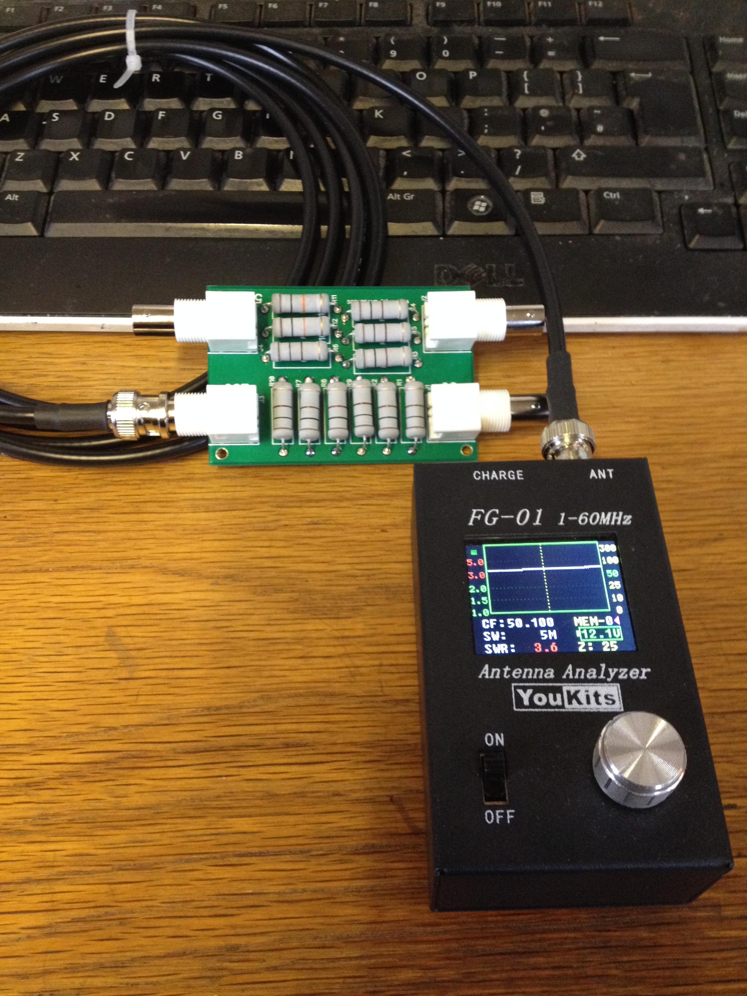
Most radio amateurs know that lossy cable tends to make the SWR look better at the transmitter than it is at the antenna. This effect can be used to measure the loss of a cable. The method requires a load that will give a high SWR and an SWR bridge (or antenna analyser). The load is first connected directly tio the SWR bridge and the SWR recorded. It is then connected to the far end of the feeder (perhaps up a tower) and the SWR is measured in the shack. Choice of the mismatched load is important if good results are to be achieved. The most extreme mismatches would be open or short circuits. These rather special conditions give a theoretical infinite VSWR. Most SWR meters are inaccurate at very high VSWR readings, thus a better choice of mismatch is a load that will give a VSWR of between 2:1 and 5:1. these values are much easier to read accurately. In our case we used a BOXA-TEST which contains for different test loads - very handy for all sorts of testing! The BOXA-TEST has a 5:1 load and this was used to measure the cable loss. The measurement was very simple to do.

First the BOXA-TEST 5:1 port was connected to an antenna analyser and the VSWR checked at 50MHz. It measured 4.6:1. Next the test cable was measured with the BOXA-TEST on the end. Now the VSWR was 4.0:1. Calculating the cable loss is now a matter of turning these VSWR readings into return loss.
Professional engineers seldom use VSWR as a measurement as return loss is more useful. Return loss is the power loss due to a signal travelling to the end of a line and being reflected back. A matched line connected to a perfect dummy load would show an infinite return loss - no reflected power. A mismatch will reflect (return) some power. VSWR readings can easily be converted into return loss in dB using this online resource at Telestrian LINK.
In our example 4.6:1 = 3.84 dB rl. 4.0:1 = 4.44 dB rl. The difference is twice the cable loss so the cable loss is 0.3 dB. In a few minutes I was able to check the whole cable assembly and the connectors. As it was, the cable was fine so my friend will need to look elsewhere for the source of his problem.
This is an easy measurement to make and it's a good idea to do this measurement when installing new cables. Make a note of the readings and then you can check your cable every year or two to see if its loss remains constant. If you are doing this, also make a note of how you made the measurement - especially what equipment you used. Use the same measuring set-up each time for a consistent comparison.
If you enjoyed this post you may like to know that we publish an occasional newsletter.